Plandroid - Graphical Air Conditioning Design and Quoting Software
Plandroid Help Documentation
Designing With Rigid Ducts
Plandroid has excellent support for rigid duct designs. You first need to ensure that
you have a catalog loaded that contains rigid parts for you to use, for example
the Generic Rigid Duct catalog. There are both rectangular and round rigid duct parts. Some rigid
duct parts are user drawn, and some are resizable using
resize handles ( ), and some are modified by either editing their parameters or using handles.
 |
The Generic Rigid Duct catalog, for example, has a wide range of rectangular ducts, round ducts, round take-offs, and adjustable starters that you can use in your design.
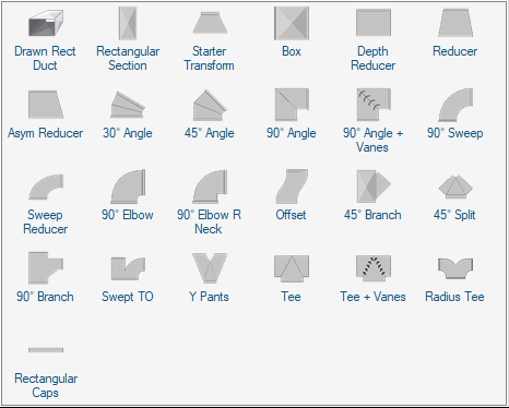 |
This catalog also has a range of adjustable starter sets that can also be resized and priced by material in the same way as the rigid duct parts. Boxes include return air boxes that can likewise be set to any size.
The catalog will show a range of part sizes to chose from, but this is only a convenience. You can set any part to any size - you are not limited by the sizes presented in the catalog.
You Can Set the Size of Any Duct or Joiner
The size of any rectangular duct can be set by selecting it and using the context menu item Set Duct Dimensions if it is a simple rectangular section, or Edit Rigid Connector if it is a more complex item. Double clicking on a rigid connector will also give you direct access to its parameters:
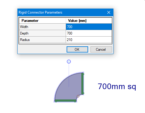 |
Most geometrical parameters (those that are not a connector Width or Depth) also have handles
() that let you directly edit the parameter on the part, for example
the radius handle in the example above.
Rigid Ducts Can Automatically Size Themselves
When adding rectangular rigid duct components to the design canvas, they will automatically resize to fit any other rectangular connector on a part already on the canvas if the Dynamic Part Resizing option is selected. The Generic catalog has a range of sizes for each type of part for convenience, but you can usually just drag any size into the canvas and it will connect to any other part. So you normally only need to set the size of one duct to start building your design. When connecting two parts, the rule is: the part that you are moving is the part that will resize itself to fit a part that is not moving.
Rigid Ducts Can Regenerate Their Own Product Codes
A rigid duct that has been modified from its default size needs to have a different product code so that it can be distinguished from the default sized part. The program will automatically update the product code of a rigid part when required so that it's product code is consistent with its dimensions.
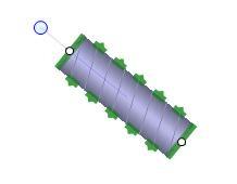
You Can Connect Duct Side Branches to Drawn Rigid Ducts
You can connect flexible rigid duct at any location on the side of a user-drawn duct, so long as the height or diameter of the part is no greater than the height of the rigid duct.
Drawn rigid ducts can also take round or rectangular outlets directly on their sides or bottom surfaces.
Flow calculations are performed taking into account the relative position of any side branches or outlets.
Rigid Ducts Can Have Different Draw Styles
Like many items, rigid ducting can be drawn with different Draw Styles: Filled, Outline, or for some parts 3D style. Right-click on the selected parts and use the context menu item Draw Style to set the style or to set the default style.
In the following image, the top three duct systems are priced by components while the bottom three systems are all priced by material (see below) which gives them a hatched overlay. The first column has a 3D draw style, the middle column has a Filled draw style, and the last column has an Outline draw style.
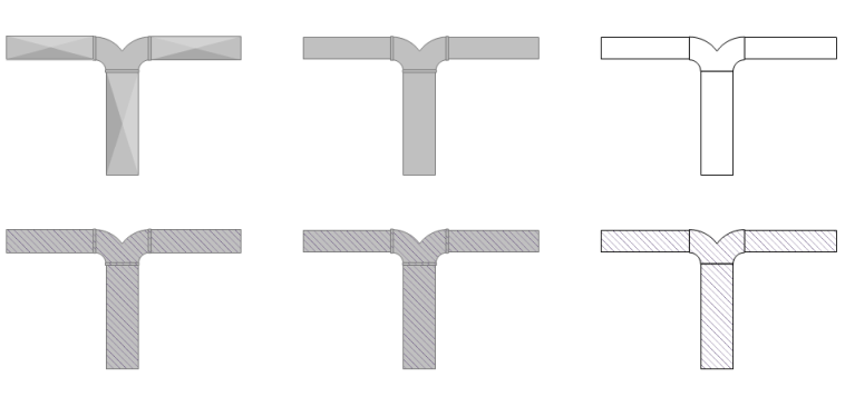 |
As you can see, the material hatching style will override a 3D draw style given to the ducting.
You Can Automatically Dimension Your Rigid Ducting
Use the context menu item Add Dimensions on a selection of rigid ducts to automatically add dimensions to those parts:
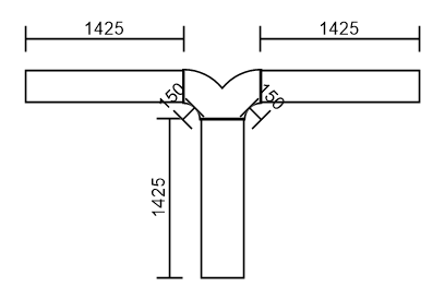 |
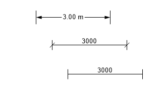
As with the ducting, select the dimensions themselves to modify their draw styles, or set the default draw style, with the context menu item Draw Style.
 |
Using the Automatic Designer with Rigid Ducts
The automatic designer does not currently support designing with rigid ducts.
However, you can still do a flow analysis on an existing design with rigid ducting using the Solve Air Flows toolbar
button ( ). Click on any part to see its air flow displayed in the
status bar.
). Click on any part to see its air flow displayed in the
status bar.
Material-Based Costing
You Can Cost Your Design Based on the Materials Used
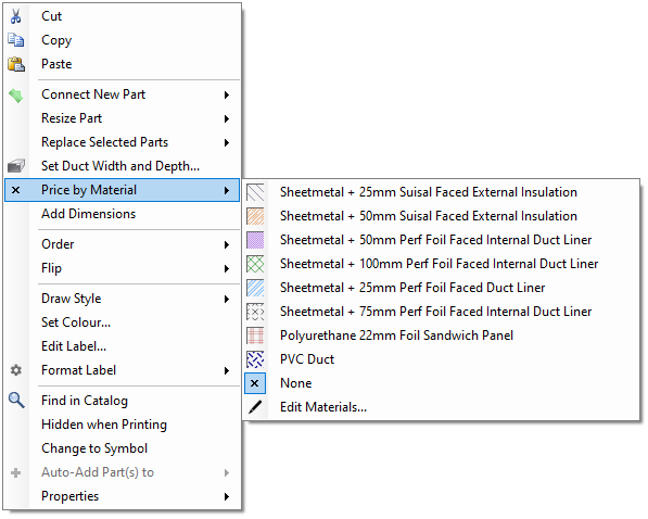
Normally parts are costed individually. However, most rigid duct components can instead be priced by the material used in their construction. Selecting a part and using the context menu item Price by Material to allocate a material type to the part will cause it to be priced by the surface area of the material used. Selecting a material type of None will cause it to be costed as an individual part again.
 |
Right-click on the duct and select Properties to see all the properties of the duct including its material, surface area, and pricing.
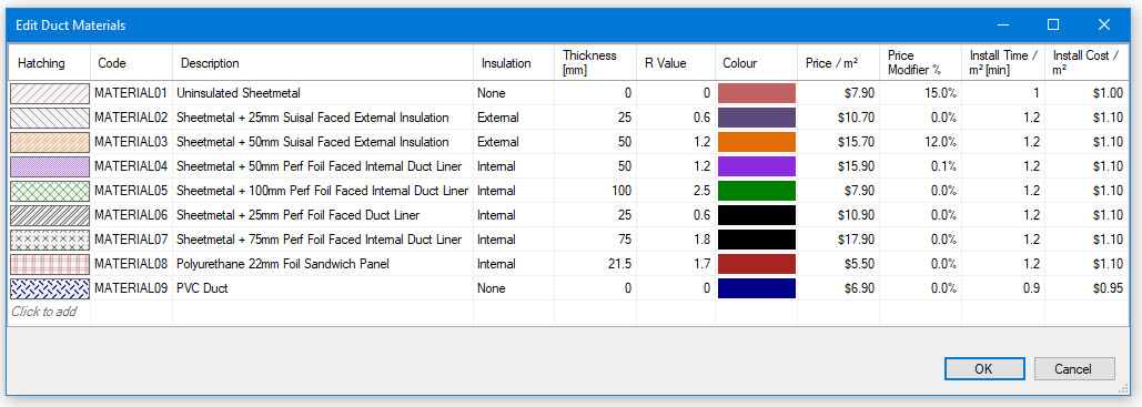
Editing Materials
You can edit the available material definitions on your system with the context menu item Price by Material -> Edit Materials. You can add new material definitions or delete definitions that you don't want to use. The definition includes a unique material product code, the hatching style and colour to draw with, the price per area for that material, and other properties. The material hatching style will override any other draw style given to the part, unless you are using a material that has been defined with the style Use Draw Style, in which case it will be displayed in its given draw style instead.
 |
Material Manufacturers
When pricing ductwork by material, it is normal for many different parts to contribute to the total material used. It is possible that the parts may not all come from the same manufacturer. The material is not separated according to different part manufacturers, but is only grouped by the material's product code. The manufacturer of the material, as used in the Costing Page, will be taken from the first part the program finds using that material and applied to the entire material.
Loading Files With Materials
When you load a file that uses materials the file will include data on those materials, and it may use a different set of materials to what you have defined on your own system. If you have a different material definition on your system that uses the same material product code, the program will use your own definition for the material instead of the definition in the file. If the material definition in the file is a new material definition (that is, it has a new product code), it will add the new material to your own material definitions list so you can use it again. If you want to use the material definitions in a loaded file instead of your own, just delete your own definitions before you load the file.
To remove any unwanted material definitions, simply open the Edit Duct Materials table, select the unwanted definitions and press [Delete].
Go back to How do I?