Plandroid - Graphical Air Conditioning Design and Quoting Software
Plandroid Help Documentation
A file that represents a catalog in the editor is marked with the  symbol to differentiate it from a definition file.
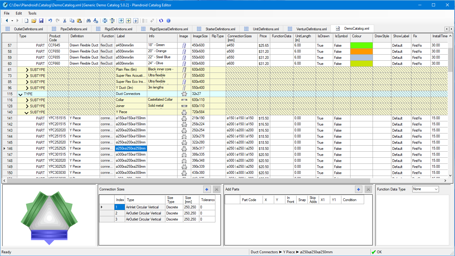
Catalogs are edited in a catalog tab as shown. The catalog tab contains the following panels:
- Catalog Grid - the top section displays the part TYPE, SUBTYPE and PART hierarchy with the properties for each entry.
- Part Preview - the bottom left corner displays a large preview of the selected part. Double click on the preview at any time to locate that part in the Catalog Grid.
- Connection Sizes - displays and allows editing of the Connection Sizes for the selected part.
- Add Parts - displays and allows editing of the Add Parts for the selected part.
- Function Data - displays and allows editing of the Function Data for the selected part.
 |
Each row in the catalog grid represents a part type, subtype, or a part. The Type entries TYPE and SUBTYPE are marked with arrows (⮛ and ⮚) which can be clicked to open and close those sections to help in navigating through the file.
The Catalog Grid
Adding and Removing Types, Subtypes, and Parts
You can add new items with the Add Part Type ( ) Add Subtype (
 ) and Add Part (
 ) buttons. Adding a new part type or subtype will add it to the next legal position, which may
be after the currently selected item. If you want to insert a new row where you are, possibly splitting the current selection, then hold down [Ctrl]
with the button to do an insert add. Note that newly created items will have
some cells shown in red meaning that they must be filled in for the item
to be legal.
) buttons. Adding a new part type or subtype will add it to the next legal position, which may
be after the currently selected item. If you want to insert a new row where you are, possibly splitting the current selection, then hold down [Ctrl]
with the button to do an insert add. Note that newly created items will have
some cells shown in red meaning that they must be filled in for the item
to be legal.
To remove items, select the whole row of the grid by clicking in the left most column that contains the row numbers and hit the Delete key.
Editing Types, Subtypes, and Parts
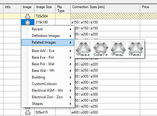
Many cells use the right mouse button and the left mouse button to perform different actions. You edit properties of part subtypes and types by left clicking on the cells in the parts grid. The Definition and Image columns have a special drop-down selector that lets you choose from given values, that you also access by left clicking on a selected cell. Right clicking will bring up the context menu, as normal.
Hold down the [Ctrl] key when viewing the Definition or Image selection menu to also preview the item names.
 |
Hatched cells indicate properties that do not apply to types and subtypes and so cannot be edited. Also, the part's function cannot be edited as it is determined by the part's definition.
See the description of all the properties of parts to understand what the property values mean.
Connection Sizes, Function Data and Add Parts can also be edited in the panels below the parts grid as described below.
Creating Parts
To get a part to look and behave as you wish, you need to assign the right Definition to it, and also the right Image. The definition largely determines how the part behaves—if the part carries air, refrigerant, or electricity, which and how many connectors it has, if it is drawable or resizable, plus many other characteristics. Setting the image icon for the part determines how the part appears in the catalog and on the canvas. A part will use the icon from its definition by default, but you are free to change it to any icon you wish. The image size determines how large the part is when viewed from above in a plan view.
Sometimes parts that use the same definition look the same or similar—for example Y Pieces are all instantly recognisable. In this case, the appropriate definition is easy to find as its menu image will be the same as the part you are creating. However, in many cases a part definition can look completely different to the part you want to create—for example most symbols use the part definition Resizable Icon but have wildly varying image definitions. It may not always be simple to find the appropriate part definition from its default image if it does not match what your physical object looks like, even though its behaviour—and therefore the definition you want to use—will be the same. If you can't immediately find the definition you need, it is often helpful to find a similar part in an existing catalog, and then use the context menu item Go to Definition on that part to locate the right part definition.
Subtypes Can Be Concatenated
Subtypes that have the same name will be concatenated—that is, their constituent parts will be grouped together into the one subtype. In this way similar parts can be conveniently grouped together in separate groups in the catalog file but displayed in one subtype in the Plandroid catalog.
Label Fields Can Have Dynamic Tags
If you add one of the dynamic tags into a part's label, that label will update dynamically to show you dynamic data in the Parts catalog or in the canvas, as appropriate. Dynamic tags have special delimiter characters, and include: «Flow», «Flow With Units», «Width», «Height», and «Radiator Power». Right-clicking to bring up the context menu will give you an option to insert a dynamic tag into a label.
Info Fields Can Have Carriage Returns
An Info (tooltip) field can span multiple lines. You can add a carriage return by using [Shift] + Enter while you are editing this field.
The Image Size Field Supports US Units
The Image Size field only supports mm as units, but when entering data into this field, you can also enter data in inches so long as you add " to signify inches at the end of the string, for example 12.75x14". The program will automatically convert the data into mm.
The Mouse Wheel Edits the Image Size
You can use your mouse wheel to scale an image size after it is selected. Holding down the [Shift] key while you scroll will make the value change in large steps.
Collapsing and Filtering
The parts grid supports collapsing and filtering so that you can find and focus on the parts you are editing.
Types and Subtypes can be collapsed by clicking on the TYPE or SUBTYPE
cell in the Type column. Clicking the cell again will uncollapse it. The
arrow shows the current state. There are also Collapse Part Types ( ) and Collapse Subtypes (
 ) buttons on the toolbar to toggle the
state of all part types and subtypes at once, plus range selections can be opened and closed using the context menu.
) buttons on the toolbar to toggle the
state of all part types and subtypes at once, plus range selections can be opened and closed using the context menu.
The parts grid can also be filtered on any column. Left click on the column heading to display the filter menu. When a filter is active on a column the column heading is highlighted with a yellow background.
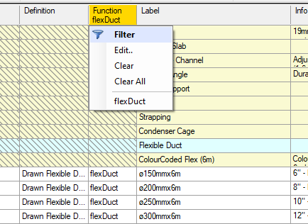 |
You can have a different filter on each column. Items that do not pass the filters selected will not be shown until the filters have been cleared.
Drag and Drop Editing
The program supports drag and drop re-ordering of items, but you must drag a selection by its row number cell. Hold down the [Ctrl] key to copy the selection that you're dragging.
Copying and Pasting
You can copy and paste data between the editor and other programs, for example a text editor or Excel. Cutting, copying and pasting are accessed through the toolbar, main menu, right click menu or standard keyboard shortcuts ([Ctrl] + X, [Ctrl] + C, [Ctrl] + V). It is often quicker to perform edits on multiple items at once in a text editor or in Excel, and this functionality makes it easy to do that.
Two types of pasting can occur, value pasting where the values of the selected cells are changed and insert pasting where new parts, subtypes and/or types are inserted as new items. When copying from and pasting back to the catalog editor, inserting will automatically occur if a whole row is selected when performing the paste. Click the leftmost column, which contains row numbers, to select a whole row.
It is also possible to choose Insert Paste on the context menu. When data is copied to another program, a heading row (for example [ProductCode]) is included that shows the columns that the data came from. The heading row can be included when pasting the data back into the catalog editor, and for an insert paste it will be used to put the data into the correct column.
The Preview and Editing Panels
You can edit information directly in the catalog grid, but some information is also shown more clearly in the preview and editing panels that are shown underneath the grid. Click on the preview image at any time to go back to that part if you have scrolled past it in the catalog grid.
Editing Connection Sizes
The connection sizes for the selected part can be edited in the Connection Sizes panel. See the description of connection sizes to understand how they work.
A size is a pair of numbers joined by an x, for example 200x150. Each connection may have multiple sizes listed, depending on the Size Type. For each size the first number is the width and the second is the height. For circular connections (except for a perimeter) the width and height should be the same.
- Discrete - For discrete sizes there can be any number of alternative sizes, separated by a comma (,).
- Range - For range sizes there are two sizes. The first value pair specifies the minimum width and height and the second value pair specifies the maximum width and height.
- Perimeter - For perimeter sizes there is one size. The width specifies the minimum perimeter and the height specifies the maximum perimeter.
Note that the type of the connection comes from the part definition and so cannot be edited. It is included for reference, to help you understand the connections correctly.
A 'd' can be used when entering connection sizes to represent a diameter symbol 'ø'. You can paste connection size information in multiple formats - the program will try to interpret your data so that it corresponds to the connectors on the part. For example 450/400-400/350/300-250/200 for a part with 3 connectors will be translated into the equivalent standard format ø450,ø400 | ø400,ø350,ø300 | ø250,ø200, while 150/200/250 will be translated to ø150 | ø200 | ø250 for a part with 3 connectors, but to ø150,ø250,ø300 for a part with a single connector.
The connection sizes are entered in the units specified in the Catalog Properties ( ) -> Measurement Units -> Connection Sizes field.
Editing 'Add Parts'
The add parts for the selected part can be edited in the Add Parts panel. See the description of add parts to understand how they work. Multiple parts can be added. Values are edited by left clicking the cell in the grid. You can edit the following fields:
- Part Code - The product code of the part to add when the original part is added to the canvas.
- X - The X-offset of the added part, relative to the original part.
- Y - The Y-offset of the added part, relative to the original part.
- In Front - True if the added part is added in front of the original part.
- Snap - True if the part should snap to any connectors when it is added.
- Skip Adds - True if the part should skip any recursive additions.
- X1 - For drawn parts, the X-offset of the far end of the part.
- Y1 - For drawn parts, the Y-offset of the far end of the part.
- Condition - If present, a special condition code that determines if the part is added.
Editing Function Data
The function for the selected part can be edited in the Function Data panel. See the description of function data to understand how this works. The part's Function determines if it requires any Function Data, and you can only define it for those parts. The type of function data for the part is selected using the drop down and appropriate tabs will appear to edit the data. The following types of function data can be added:
- Fan
- Fan Coil
- Heat Exchanger
- Light
- Radiator
You can specify the fan performance as a fixed rated airflow output, which assumes a constant pressure, or for better accuracy you can enter a fan performance curve of airflow as a function of the external static pressure. If you enter curve data, the editor will display a plot next to the function data panel showing your data points and the smooth polynomial curve fit to those points that the program will use when interpolating between the data points.
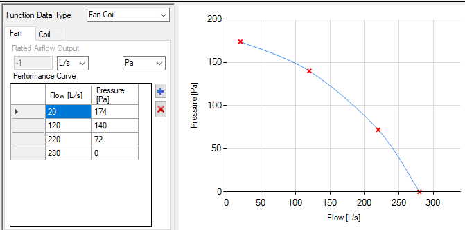 |
Enter the performance data from the smallest to highest flow rate. Note that you can select whichever air flow and pressure units make it easiest for you to enter your data.
Tools
Menu Item Tools
Several tools are available from the Tools menu item:
Add Local Definitions - Adds local part definitions to the current catalog file. Local definitions are included in the current catalog file and are not usable by any other catalogs.
Check All Catalogs - Performs a check of all files in the catalog directory and displays any errors.
Open in XML Editor - Opens the catalog or definition file in the default editor for XML files so you can directly edit the underlying text (for advanced users).
Send for Signing - Sends your edited catalog to us so that we can check it and then add a digital signature so that it can be used normally.
Bulk Editing Operations
Smart Paste - This powerful tool lets you copy data from Excel, another catalog, or a text file and past it into the editor so that it will both update any existing parts with the same product code, and add new parts if the product code is not present. It will also give you the option to mark for deletion any parts that are present in the catalog but not in the pasted data. This is especially useful for maintaining existing catalogs when you have updated product data provided in a spreadsheet. Similar to when you have an optional header when you copy and paste text, with Smart Paste each imported column must have a header row with the appropriate column titles, including at a minimum a product code column. For example: [ProductCode], [Price], [Info], etc. (Each column header title is shown in the header tooltip in the editor). Any column that does not have a recognised header title in the selection will be ignored.
All data in the clipboard selection will replace the existing data in the catalog editor with the exception of the [Info] column, which will only be set for new parts. Existing parts will not have their [Info] data overwritten. It is usual to exclude the [Label] field, so that any new parts are immediately visible in the editor due to the required missing Label field being highlighted.
Reprice Catalog - edit part prices in your catalog by opening a tab-delimited text file with the header line Part Price (and optionally Discount) that contains the new prices for each part. Repricing can of course also be done with the Smart Paste function - this is just an alternative method.
Map Product Codes - Map product codes from one system to another by opening a tab-delimited text file with the header line Part New, where the New column contains the new codes to be used in place of the old codes.
A Reprice or Map file can have other columns, which are ignored. When using these file-based bulk-editing operations, the first item in any row can have a special entry to control how the file is processed:
- * - Skip this row
- BREAK - Skip this and all subsequent rows until a CONTINUE item is found
- CONTINUE - Begin processing from this row onwards
- END - Finish reading the file
A part in a reprice file with a Price of POA will have its price set to 0. Any part with the Price value of DELETE or -999 will be deleted from the catalog.
Similarly any part in a map product codes file with a New value of DELETE will be deleted from the catalog.
Toolbar Tools
Tools available from the toolbar include:
Navigate Forwards and Backwards ( ) - these let you easily find the different places in your open documents that you have touched recently.
Sync to Parts ( ) - Saves all the files that have been modified and reloads
the catalogs into Plandroid. Note that the catalogs must be selected in
Plandroid for reloading to have any effect.
) - Saves all the files that have been modified and reloads
the catalogs into Plandroid. Note that the catalogs must be selected in
Plandroid for reloading to have any effect.
Catalog Info () - Opens a dialog for you to edit the
metadata for a file. This includes the name and version number of the catalog, information about the
manufacturer, and the dates that the catalog is valid for. The Catalog Type tells the program if it is
a catalog of parts or units (or both), which is relevant for users who have a locked licence.
Context Menu Tools
While some columns have a drop-down editing selector that that you access by left clicking a cell, you open the context menu by right clicking on a selection, as normal. A number of tools are available from the context menu in the editor:
Generate Label from Sizes - Sets the label for a part from the sizes of its connections. Circular connections use a single value with a diameter symbol (e.g. ø150) and rectangular connections include the width and height (e.g. 250x250). Non-air connections on an air conduit part, such as damper blade connections, are ignored.
Generate Label from Function Data - Sets the label for a part from its function data. The label format is specific to each type of function data.
To Title Case - Change text in the selected label or info cells to 'title' case - Where All Words Start With an Upper Case Letter.
Transpose Sizes - Swaps the width and height values for an image size or rectangular connection sizes.
Sort by Size - Sort the selected items by their connector size or image size. Rectangular sizes are sorted first by width and then height.
Set Image Size from Connections - Sets the image size of the current part by scaling its size against the part definition using the relative sizes of their connection sizes.
Scale Image Size - Apply a width or height scaling factor to all the selected image sizes.
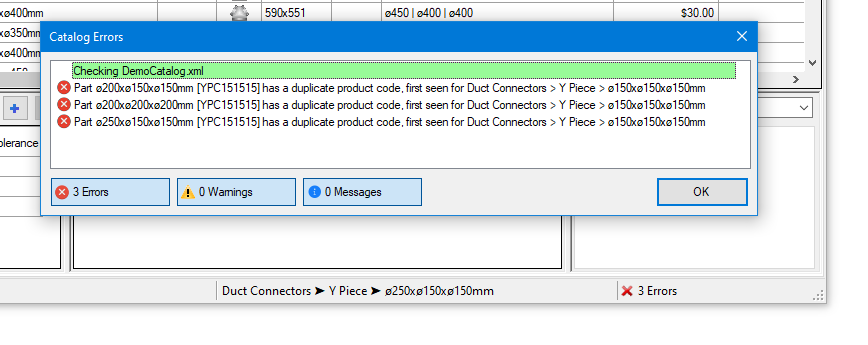
Checking Your File
The status icon, on the right-hand side of the status bar, will report the number of errors the editor has found in your file, if any. Click on the status field to bring up a dialog showing each error. Double click on any error entry to go to the location in the file that is causing that error.
 |
Tips, Tricks and Style Conventions
To keep the catalogs consistent and intuitive we employ a number of general stylistic conventions which it is advisable to follow as far as possible.
Keep Labels Concise
As a part's label is often shown on the drawing canvas, labels that are too long will look messy and cluttered when displayed. Try to keep a part's label as concise as possible, for example just the connection sizes for connectors, or the minimum unique identifier for other parts. Do not repeat information that is already shown in the part type or sub-type name in a part's label.
Air Flow Direction is Up
If a part transports air or water, then by convention we have the medium entry at the bottom of the icon and the outlets towards the top.
Prefer Wide Parts to Tall Parts
When the airflow direction is not relevant, most icons are designed so that they are wider than they are tall. Parts like boxes and grilles will look best if they keep to that convention, so consider rotating tall parts.
Order Parts from Small to Large
When ordering parts in a Subtype group, place the smaller parts first, and order them by size up to the largest parts. There is even a context menu item to help with this: Sort by Size.
Group Like Types Together
Parts are easier to find if similar or related part types or subtypes are located close together in a catalog. Putting grilles close to boxes, dampers near Y-pieces, and return starter sets near supply starter sets will all make your catalog easier to use.
Keep Group Sizes Reasonable
While it is not always possible, it is good to aim to keep groups of items (part sub-types or parts) to a manageable size of something like 7-10 items. Often, if there are more parts than this that is a sign that you may need to split them into different sub-types, or similarly, if you have just one or two parts in a sub-type, then that is often an indication that you may need to find similar types of parts to group together.
Some Icons Require Scaling
A few icons need to be larger than the actual part they represent. For example, some outlets or units also include air flow arrows. These icons need to be given a size that is larger than the actual part to include the arrows. Icons can be scaled along any axis with the editor context menu command Scale Image Size.
Make Sure Special Parts Have Function Data
If you are adding a fan coil unit, for example, make sure you have also added its performance characteristics into the catalog using the Function Data fields. This is what makes the part behave like a fan coil unit when analysing the design. Similarly for heat exchangers, lights, and radiators.
Editing Data in External Programs is Useful
Don't be reluctant to copy and paste data between the editor and external programs such as text editors or Excel. While the editor itself is powerful in many respects, tasks such as editing columns of data are much more easily done in a good text editor by copy and pasting the data between programs. We recommend Notepad++ as a powerful but free text editor that supports column editing, macros, regular expressions, and a wide range of other functions.
Use the Catalog Version Number to Keep Track of Your Edits
The Catalog Properties -> Version number is made so that you can keep track of your edited files. The first released version should be 1.0.0, and then update this number whenever you release a new version of your catalog. Normally we change the first digit when there is a major change or rewrite to the catalog. We increment the second digit whenever new parts are added or removed, and the third digit represents any other minor changes such as small pricing changes or other small tweaks.