Plandroid - Graphical Air Conditioning Design and Quoting Software
Plandroid Help Documentation
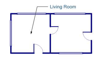
Annotate With Arrows and Notes
You can add a note by simply copying text and pasting it directly into the canvas, or you can add notes and leader arrows to your design with the Design -> Draw -> Add note tool. Click and drag the tool to add a leader arrow to your note. Double click on a leader arrow to add a bend point. Double click the Select tool on an existing note to edit it.
 |
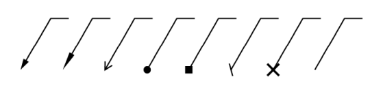
Arrows and Notes are Highly Configurable
You can use the Arrow Angle and Arrow style tool settings to control the angle and look of your leader arrows:
 |
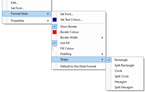
Leader arrows and notes are very customisable so you can make them look exactly how you want. Use the context menu item Format Note to change the border style and colour, fill, padding, and border shape of the note.
 |
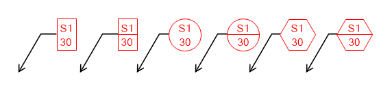
Configuring Note Shapes
You can select from rectangular, circular, and hexagonal note border shapes. Each has a split option for when you want to have a border between two lines (simply use a carriage return in your note to put text on the lower split).
 |
Part Labels Can Have Dynamic Tags
Part labels have the same formatting options as notes. A part can have a label that displays its data dynamically on the canvas. In the Edit Label dialog, clicking on the Insert Field drop-down arrow (circled below) will show you the type of data that you can insert into a label:
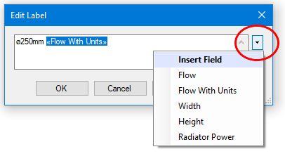 |
The name of the data field will be shown as a tag between the special characters: « and », and this field will be updated dynamically with data from your design. This lets you show a part's air flow, width, height, or radiator power (depending on what type of part it is) in that part's label.
Go back to How do I?