Plandroid - Graphical Air Conditioning Design and Quoting Software
Plandroid Help Documentation

Refrigerative Cooling Systems
A refrigerative cooling system is a heat pump that works by compressing a refrigerant fluid from a gas into a liquid in a compressor, which heats the fluid up so that the waste heat can be discharged into the outside environment. The resulting ambient temperature liquid is then transported inside a building where it is expanded back into a gas inside a coil. This absorbs heat, cooling the coil, and also air that is passed over the coil. The refrigerant absorbs heat from the air during this process, and is then passed back to the compressor, completing the cycle. If the compressor is in a separate location to the coil, which is typical for modern systems, this is known as a split system.
Refrigerative systems have the advantage that they can remove humidity from the air while it is being cooled, which means that they can work in virtually all weather conditions. Their disadvantage is that they are energy intensive, and therefore relatively expensive to run.
A refrigerative system will recycle most of the same air through the building, which means that if outside fresh air is required, that will have to be explicitly designed into the system. It also means that the design must incorporate a return air path, usually including filters to clean the recycled air.
Very often refrigerative systems are designed so that the heat cycle can be run in reverse, pumping heat into the building when heating is required. In this case the system is referred to as a reverse cycle system. Such a system is efficient because it can pump significantly more heat into a building that the energy it takes to run the heat pump.
Designing a Refrigerative Cooling System
You can select the refrigerated design mode ( ) with the
Design -> Loads -> Design mode drop-down button.
) with the
Design -> Loads -> Design mode drop-down button.
You should ensure that you have loaded suitable catalogs that include ducting, outlets, refrigerative units, and starter sets when you do a design in the refrigerative design mode.
For a refrigerative design, a unit is selected based on both the cooling power it can supply, and the volume of cooled air that it can deliver. A refrigerated system typically requires at least 8 to 10 air cycles per hour. You can adjust the required air flow settings to use under the Options -> Design -> Design Modes -> Refrigerated mode:
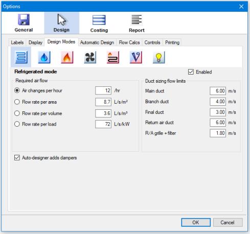 |
The duct sizing flow limits settings are used when you are using the Automatic design toolbar tool ( ),
or the Auto-size Ducts toolbar tool (
),
or the Auto-size Ducts toolbar tool ( ) to calculate the required duct sizes. The duct is sized so that its maximum air flow velocity does not exceed the given value
based on the duct's position in the system. Typically, the air should move more slowly as it gets closer to an outlet so that airflow noise does not
become significant.
) to calculate the required duct sizes. The duct is sized so that its maximum air flow velocity does not exceed the given value
based on the duct's position in the system. Typically, the air should move more slowly as it gets closer to an outlet so that airflow noise does not
become significant.
The duct size flow limits that you can specify here represent a trade-off between material costs, running costs, and noise. Smaller ducts use less material and therefore require less capital outlay. However smaller ducts also result in higher air flow velocities which result in extra noise and higher running costs. You might consider tuning these factors to use smaller ducts (higher velocities) if you are somewhere where electricity is cheap and ductwork is expensive, and likewise you might use larger ducts (lower velocities) if you are in a location where electricity is expensive and duct componentry is more affordable.
Fan coils can have pressure vs. flow rate performance curves defined, so that when used with the analytical flow solution accurate flows can be calculated that take into account the pressure loss of your system.
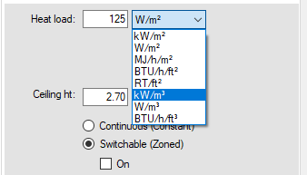
When laying out the heat load zones in any mode, the program typically supports multiple methods to calculate the resulting heat loads. Heat loads can be specified as either loads per area or loads per volume. To change the method, simply select the units that correspond to the method you wish to use in the Loads tool tab Heat load setting. For example, if you select your units as W/m², you will be specifying your loads per area. If you select W/m³ you will be specifying your loads per volume.
 |
If you know the resulting load and don't need the program to calculate it for you, you can instead set the load directly by right-clicking on the zone and selecting the context menu item Set Zone Load.
When designing a refrigerative system, the outlets are normally placed towards the outer edge of the building. Thus the walls and windows are cooled where the outside heat is entering the building. The air then flows back towards the centre of the building where the return air intake is typically located in a common area such as a passageway.
A fan coil will normally need a starter set to allow ducting to connect to the unit. The conditioned air from the fan coil unit will be channelled into the supply ducting via a supply starter. The return air will be guided from the return air ducting into the unit's intake via a return starter. Such a ducted system requires outlets and vents to distribute the air. It is also possible to deliver conditioned air directly into a space using a wall unit, cassette unit, or bulkhead unit, for example, without any ducting. In Plandroid you can also place these units in a zone and their capacity will also be calculated.
Copper pipe or pair coils can be connected between the indoor fan coil and the outdoor condenser unit in Plandroid. This can be done to illustrate the pipe runs, to calculate the pipe run lengths, or to calculate the total connected unit power in VAV (multi-head) systems. However, it is not a requirement to connect your units and the program will assume the units are appropriately connected for any calculations it performs.
Go back to Design Modes overview.